The current resolution of the ACS758 family of current sensor ICs is limited by the noise floor of the device output signal. For example, the ACS758-050 version can resolve a change in current level of about 250 mA, at 25°C, through its primary conductor leads. The 200 A version can resolve approximately 380 mA. At these levels, the amount of magnetic field coupled into the linear Hall-effect IC is just above its noise floor. Resolution can be improved significantly by filtering the output of the ACS758 for applications requiring lower bandwidth. Table 1 lists the noise levels, and hence current resolutions, at various bandwidths. Filtering was accomplished with a simple, first order RC filter. Note the related graphs, figures 2 through 5, which provide a better understanding of the device output resolution that can be achieved through filtering.
Table 1. ACS758 Noise Level and Current Resolution versus Bandwidth |
||||
|---|---|---|---|---|
| Device | Bandwidth -3 dB (kHz) |
Noise (mVp-p) |
当前的解决方案 | |
| (嘛) | (% of full scale) | |||
| ACS758-200B | 120. | 3.84 | 384. | 0.。192 |
| 10. | 0.。92 | 92 | 0.。0.46 | |
| 1 | 0.。55 | 55 | 0.。0.28 | |
| 0.。2 | 0.。15. | 15. | 0.。0.0.8. | |
| ACS758-150B | 120. | 4.36 | 328 | 0.。219 |
| 10. | 1。0.8. | 8.1 | 0.。0.46 | |
| 1 | 0.。52 | 39. | 0.。0.26. | |
| 0.。2 | 0.。16 | 12. | 0.。0.0.8. | |
| ACS758-100B. | 120. | 5.69 | 285 | 0.。285 |
| 10. | 1。49 | 75 | 0.。0.75 | |
| 1 | 0.。67 | 34. | 0.。0.34. | |
| 0.。2 | 0.。22 | 11. | 0.。0.11 | |
| ACS758-50B | 120. | 10.03 | 251. | 0.。502 |
| 10. | 2.95 | 74 | 0.。148 | |
| 1 | 1。0.5 | 26. | 0.。0.53 | |
| 0.。2 | 0.。43 | 11. | 0.。0.22 | |


Table 2. ACS758 Time to Valid Output |
||
|---|---|---|
| 一世P.(一种) | 0. | 50 |
| 上电时间(μs) | 8. | 10. |

Table 3. Tested Maximum ACS758 Overcurrent Levels and Durations |
|
|---|---|
| Ambient Temperature (°C) |
Maximum Current (一种) |
| 10 S,10%占空比,100脉冲施加 | |
| 25. | 350. |
| 8.5 | 350. |
| 15.0. | 260. |
| 3 s, 3% duty cycle, 100 pulses applied | |
| 25. | 450 |
| 8.5 | 425 |
| 15.0. | 375. |
| 1s, 1% duty cycle, 100 pulses applied | |
| 25. | 120.0. |
| 8.5 | 900 |
| 15.0. | 600 |
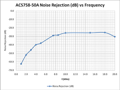
Table 4. Typical Capacitive Coupling of a 20 V Peak-to-Peak Signal on the Current Path |
|||||||||||
|---|---|---|---|---|---|---|---|---|---|---|---|
| f (MHz) | 1。0. | 2.0 | 3.0 | 4.0 | 5.0 | 7.5 | 8.。5 | 10.0 | 15.。0. | 18.0 | 20.0 |
| V.OUT(p-p)(mV) | 15.。0. | 50.0 | 10.0.。0. | 200.0 | 250.0 | 700.0 | 750.0 | 1000.0 | 1020.0 | 1050.0 | 600.0 |
| Noise Rejection (dB) | -62.5 | -52.0 | -46.0 | -40.0 | -38.1. | -29.1 | -28.5 | -26.0 | -25.8 | -25.6 | -30.5. |
